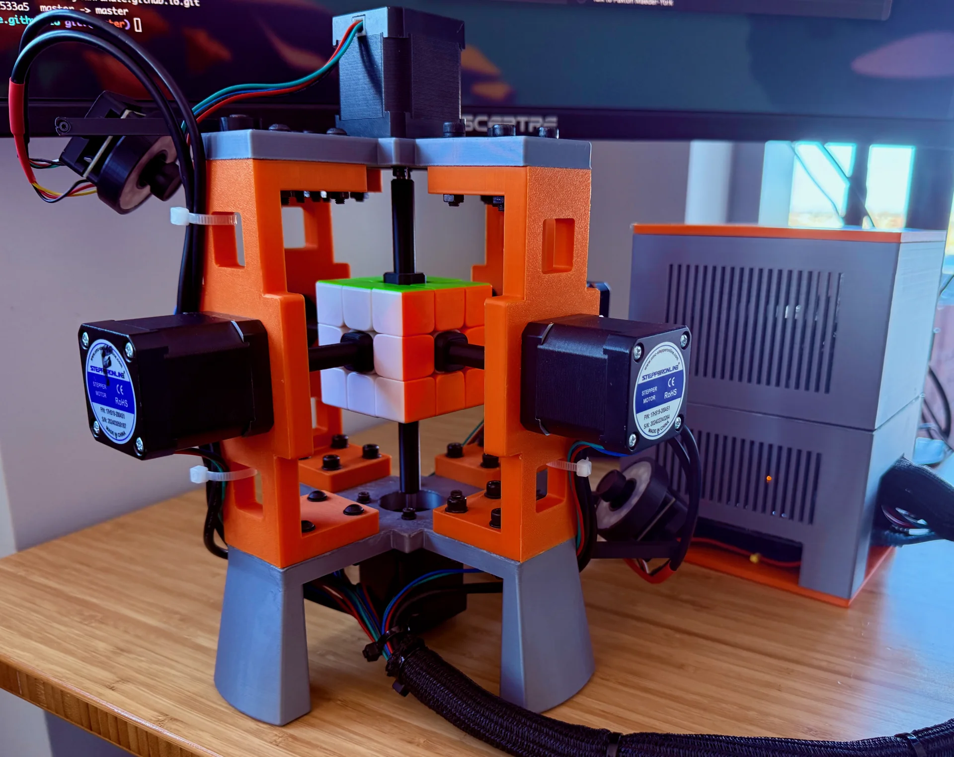
Solving a Rubik’s cube with a robot brings together three problems: observing the stickers, finding a sequence of moves, and turning the faces accurately enough that the next move is still possible. A correct solution on a computer only helps if the cameras read the right state and the hardware can execute it.
I used to solve a 3×3×3 cube in about 15–20 seconds as a kid, so building something that could beat my own times was an appealing hardware project. Most of my experience had been in machine learning and software, including software for robots. This was an opportunity to build the mechanical, electrical, and software parts of a robot together.
Approach: inspect, plan, and solve
The system passes a cube state from the perception pipeline to a solver, then sends the resulting moves to a motor controller. Each stage depends on the previous one: a misclassified sticker changes the planning problem, while a misaligned face can prevent an otherwise valid move.
Reconstructing the cube state
Two cameras positioned at opposite corners observe all six faces with help from dedicated lights. The motor shafts obscure parts of the far edges, so a single pair of images is insufficient. The robot rotates faces during inspection to expose stickers that are initially hidden, then combines those observations into the complete cube state.
The vision pipeline samples visible sticker regions and classifies their colors. I first tried fixed ranges in HSV color space, but those thresholds were brittle under changes in lighting. A K-nearest-neighbors classifier trained on labeled color samples was substantially more reliable.
The video below shows this inspection sequence at twice its original speed.
Planning the moves
Once the cube state is known, Kociemba’s two-phase algorithm computes a short sequence of moves. It first brings the cube into a restricted set of states, then solves it using a smaller set of allowed moves. The search produces near-optimal solutions without guaranteeing the shortest possible sequence.
Planning takes only milliseconds in this system. The more involved engineering work was making the observations and physical movements reliable.
Executing the solution
The planned moves are sent to an Arduino microcontroller. Six TMC2209 stepper drivers operate the motors that turn the cube’s faces by 90 or 180 degrees at a time. Those turns must end in alignment so that adjacent faces can move freely.
The robot can execute a solution in under three seconds. The main video at the top of the post shows this execution phase for a scrambled cube; the inspection sequence shown separately above precedes it.
What made the system reliable
I initially entered sticker colors manually and underestimated how much work automatic inspection would require. Improving the classifier helped, but so did iterating on camera placement and lighting. The sensing conditions were part of the perception problem: they determined what information the model had to work with.
The motors introduced a different source of uncertainty. My first setup did not adequately account for current requirements, particularly at startup, and unexpected motor movements left the faces incorrectly positioned. Rewiring with appropriate wire gauges and power supplies resolved that issue.
Startup alignment also needed explicit attention. A stepper motor can shift when energized if its resting position does not align with a full motor step. Manually moving the motors or powering down at a microstep position could leave the robot in this state. I added a command-line utility to jog the motors in full steps and restore their zero positions before operation.
Takeaway
This project made the dependencies between perception, planning, and actuation concrete. The solver could find a valid sequence quickly, but executing it required careful lighting, a reliable color classifier, adequate power delivery, and calibrated motors. Building those pieces together gave me a much better understanding of what it takes to turn a software plan into repeatable physical motion.